back
First Acoustic Camera
Software PSI-Tools
Hardware PSI-Tools
Funktionen PSI-Tools
Interferenzschaltungen
First records with AK
First Microphone-Arrays
for Acoustic Photo- and Cinematography


Fig.1: 16-chl. suitcase box "Koffer" (1996/1997), microphone MK250
First measurements showed, that open arrays have a problem. They get noise refections and noise emissions from the background just as frontal emissions. For hard industrial environments, Carsten Busch built 1996 a suitcase box in a size for the trunk of our Ford-Mondeo. It included 16 measurement microphones 1/2" Gefell MK250, a central laser pointer and the preamplifier box with power supply, Fig.2 and Fig.3.
The purpose of the laser was to show the exact central position for the optical foto for the overlay. Additionally we needed an inch rule (Zollstock) that was placed within the image for calibration. And to feed PSI-Tools, we had to measure the distance from the object.
First application of the array was the check of the noise of a car engine in January 1997 (Link). Some days later the first industrial measurement was possible at AEG Postautomation next to our company (Link). Find further measurements here.


Fig.2: 16-chnl. Koffer-array with laser (1997)
Some technical details had been stored in the first TV-report in September 1997 N3-Prisma Fig.2 and at the second TV-report about the AK at the SXF-airport Berlin-Schönefeld in February 1998 Leonardo Fig.3. The measurement occured a year before, with the old, black array in February 1997. But we made a photo of the worlds first noise-reflexion at the ground, so the Deutsche Welle TV-team ordered us to reproduce the measurement once again a year later for the TV-show Leonardo in April 1998. (The TV-team used the one year old acoustical records from SXF-airport, dated on February 1997. So in February 1998 we produced only some additional camera scenes on the airport).
There are only two fotos of measurements with the black array, one from October 1996 at AEG-Postautomation; the other photo is a measurement of the Ford Fiesta from February 1997. Probably for the the Hannover Industrie fair in April 1997 we changed the color to gray-beige. And the central laying laser was added, to have a better chance that the array looks in the correct direction.


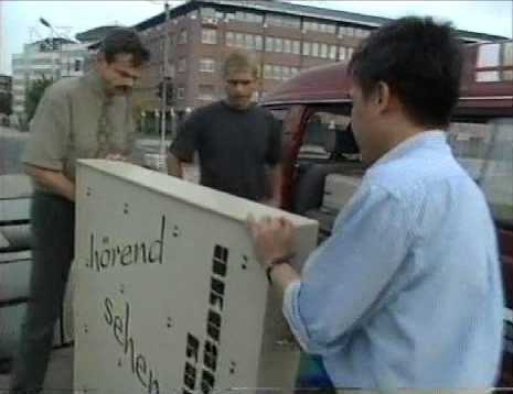
Fig.3: Working with the Koffer-array at SXF-airport 1998 together with Mark Zöllner (Hardware) and Than Tan Nguyen (Software).
In 1996 first battery-driven (4x AA-size), electronic photo-cameras appeared. I ordered a Kodak DC50-ZOOM color-camera for approx. 1500 DM. It had a resolution of 756 x 504 pixels (0,4 megapixel), a zoom optic with autofocus, an internal 1 MByte memory and a slot for a PCMCIA-card. It tooks some time, to download a non-compressed image over the serial interface RS232. The faster way was to transfer the fotos with the PCMCIA-card. (The development of USB and JPEG had just started.) Although the picture quality was poor, the use of this camera was important to get fast the optical overlay for the first acoustic images.


Fig.4: Klicker-label, Klicker2 (1999) and Kodak DC50-ZOOM camera
To set and to test the calibration of the laser direction, first we used a spark, produced by a 6 Volt ignition coil from a motorbike. We developed the so called "Klicker" (no photo found from the first versions) to get a possibility, to test the array calibration at the custumer. It was used as a remote control to start the acoustic recording, or if the loudspeaker was switched on, for the laser calibration and for the calibration test.
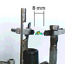


Fig.5: Acoustic image and film of sparks and spark generator
Using the Koffer-array we learned something about aliasing patterns. The rectangular arrangemant of the microphones brought an regular aliasing pattern. The acoustic photos look not so perfect, if you have lots of small sources.
So next arrays had circular arrangements of the microphones if possible. In 1998 a new suitcase box with circular arrangement appeared, see Fig.6 and Fig.7. Because of some theoretical aspects concerning the small apperture at high frequencies, the decision to construct ring-like arrays was not simple. We were not sure, if it will satisfy.
But the practical results were much better, then expected. A ring-array produces a star-like interference pattern. In case of many small sources this star-like aliasing pattern shows the location of the source(s) much better.
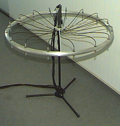


Fig.6: Radial 16-chl. Ring16 with MK301 and laser (1998)
On the other side, refective arrays have the problem of pressure-doubling compared with microphones in free field. A later measurement showed, that there are heavy differences, resulting from partial refections and the limited surface. The different distances from a microphone to the borders of the array produce heavy comb-filter effects. Any frequency compensation is complex, because the channels shows not the same comb-filter curve.
Together, we tested ring architectures and an array for the far field in 1998, that we needed for outdoor measurements. The first experiment was a 16-chl. triangle array with laser.
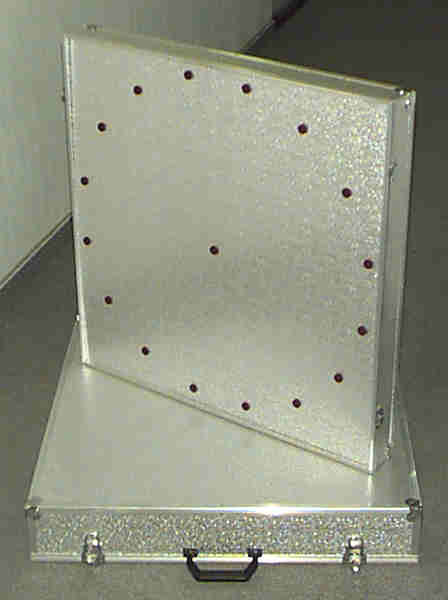


Fig.7: 16-channel Koffer-array and triangle array (1998)
Although the aliasing figures were better with the circular microphone arrangement, the new, smaller circular Koffer-array had again the problem of the refective box arrays, that one had to remove the box for the (optical) photo. It had only a central laser. The new USB-cameras came a year later.
The triangle array was foldable and compact. But the construction had an mistake. The microphone cables become very long. So this array was probably never in use. However: We learned for the next arrays.
back
E-mail: info@gheinz.de
file created Oct.10, 2002
New layout with remarks: Febr. 2023